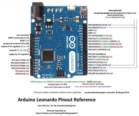
Input and Output
Each of the 20 digital i/o pins on the Arduino Leonardo can be used as an input or output, using pinMode(), digitalWrite(), and digitalRead() functions. They operate at 5 volts. Each pin can provide or receive a maximum of 40 mA and has an internal pull-up resistor (disconnected by default) of 20-50 kOhms.
In addition, some pins have specialized functions:
Serial: 0 (RX) and 1 (TX). Used to receive (RX) and transmit (TX) TTL serial data using the ATmega32U4 hardware serial capability. Note that on the Leonardo, the Serial class refers to USB (CDC) communication; for TTL serial on pins 0 and 1, use the Serial1 class.
TWI: 2 (SDA) and 3 (SCL). Support TWI communication using the Wire library.
External Interrupts: 2 and 3. These pins can be configured to trigger an interrupt on a low value, a rising or falling edge, or a change in value. See the attachInterrupt() function for details.
PWM: 3, 5, 6, 9, 10, 11, and 13. Provide 8-bit PWM output with the analogWrite() function.
SPI: on the ICSP header. These pins support SPI communication using the SPI library. Note that the SPI pins are not connected to any of the digital I/O pins as they are on the Uno, They are only available on the ICSP connector. This means that if you have a shield that uses SPI, but does NOT have a 6-pin ICSP connector that connects to the Leonardo’s 6-pin ICSP header, the shield will not work.
LED: 13. There is a built-in LED connected to digital pin 13. When the pin is HIGH value, the LED is on, when the pin is LOW, it’s off.
Analog Inputs: A0-A5, A6 – A11 (on digital pins 4, 6, 8, 9, 10, and 12). The Leonardo has 12 analog inputs, labeled A0 through A11, all of which can also be used as digital i/o. Pins A0-A5 appear in the same locations as on the Uno; inputs A6-A11 are on digital i/o pins 4, 6, 8, 9, 10, and 12 respectively. Each analog input provide 10 bits of resolution (i.e. 1024 different values). By default the analog inputs measure from ground to 5 volts, though is it possible to change the upper end of their range using the AREF pin and the analogReference() function.
There are a couple of other pins on the board:
AREF. Reference voltage for the analog inputs. Used with analogReference().
Reset. Bring this line LOW to reset the microcontroller. Typically used to add a reset button to shields which block the one on the board.
برچسبها: حسین ملکی, پیام نور شیراز, مهندسی برق پیام نور شیراز, مهندسی پیام نور شیراز
دسته بندی : علمی

- اخبار/فعالیت های انجمن علمی برق
- علمی
- اخبار تکنولوژی
- کار عملی
- قطعات الکترونیکی
- دانلود
- ابزار آلات مهندسی برق
- نمونه سوال/ پیام نور/آزاد/غیر انتفاعی/دولتی/
- نرم افزار های مهندسی برق
- فرهنگی/حدیث/طنز/حجاب
- PLC
- آموزش گام به گام میکروکنترلر
- جمع آوری پروژه های میکروکنترلری
- مدارهای کاربردی آنالوگ
- کتب و جزوات مهندسی برق
- مجلات تخصصی و مقالات
- آموزش پروتئوس
- معرفی شرکت های صنعت برق و الکترونیک
- منابع تغذیه ،شارژرها و باطری ها
- نمونه برنامه ها میکرو به زبان c و درایور ها
- آموزش برنامه نویسی
- میکرو و معرفی پروگرامر های خوب/PIC/AVR/ARM/DSPIC/
- معرفی برد های آموزشی داخلی و خارجی
- فعالیت باحال برقی

بسیجی گمنام خمینی ٍ "" و لا یحمل هذا العلم الا اهل البصر و صبر و العلم به مواضع حق ""
و این پرچم مبارزه را جز افراد با بصیرت و صبور و آگاه به جایگاه حق به دوش نمی کشند .
این وبلاگ متعلق به گروهی از سربازان حقیقی حضرت بقیه الله الاعظم می باشد که در عرصه جهاد علمی و فرهنگی فعالیت می کند .
ایمیل : malekipcb@gmail.com


 نویسنده: بسیجی گمنام خمینی
  سه شنبه سوم بهمن ۱۳۹۱ - 8:56

